Model
AYL-4
4-way
K9AY Loop System
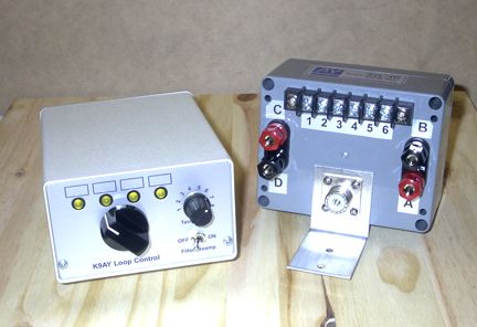
The AYL-4 is the popular K9AY Loop receiving antenna, as described in the September 1997 issue of QST, “The K9AY Terminated Loop-A Compact, Directional Receiving Antenna,” by Gary Breed, K9AY. This system provides a cardioid directional pattern in four different directions. The AYL-4 consists of two units, an indoor control box and an outdoor direction-switching relay box. The control box includes a 15 dB preamplifier with a bandpass filter covering the 160 and 80 meter bands, with excellent rejection of Broadcast Band signals and signals above 5 MHz. The AYL-4 is used with two loops installed using a single support, oriented at right angles to one another. It is intended to be used with either the AYL-M mast, hardware and wire package, or with “homebrew” loops constructed by the user.
Specifications
Antenna type: Terminated loop
Pattern: Cardioid, switched in four directions
Peak front-to-back: Greater than 20 dB, typically greater than
30 dB
Feedpoint impedance: 50 ohms nominal; low-loss transformer matching
to the antenna
Frequency range: Very low frequencies to 5 MHz, using published
dimensions
Direction change: Feedpoint/termination switching relays
Direction control: Indoor and outdoor units connected with a 6-conductor
control cable
RF connection (antenna): SO-239 (UHF) connectors at control box
and outdoor relay box.
RF connection (radio): Phono connector output to receiver external
antenna input
Termination Adjustment: Eight resistance values from 340 to 680
ohms, selected by front-panel rotary switch
Power requirements: +12 to 13.8 VDC, 400 mA max., (provided by
customer, to be fused at 0.5 A)
Preamplifier: 15 dB gain, feedback type, using a silicon NPN transistor
Filter passband: ±2 dB from 1.75 to 4.5 MHz
Filter stopband: –55 dB at 7 MHz, –50 dB below 1450 kHz
(typical)
Required Area
The AYL-4 K9AY Loop System requires 15 feet in four directions from the center
of the antenna, plus additional distance depending on the guying method. The
base of the supporting pole and the ground rod are located at the center. With
the AYL-M kit, 21 feet in each of the four directions is required. The center
support is 25 feet high, and must clear any objects above.
Click here
for K9AY Loop construction information: (HTML)
or (PDF).
Click here for AYL-4 Installation and
operating instructions (PDF).

AY Technologies * antennas
by K9AY * www.aytechnologies.com